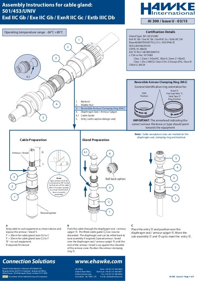
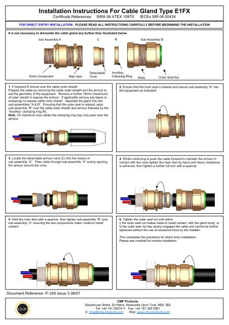
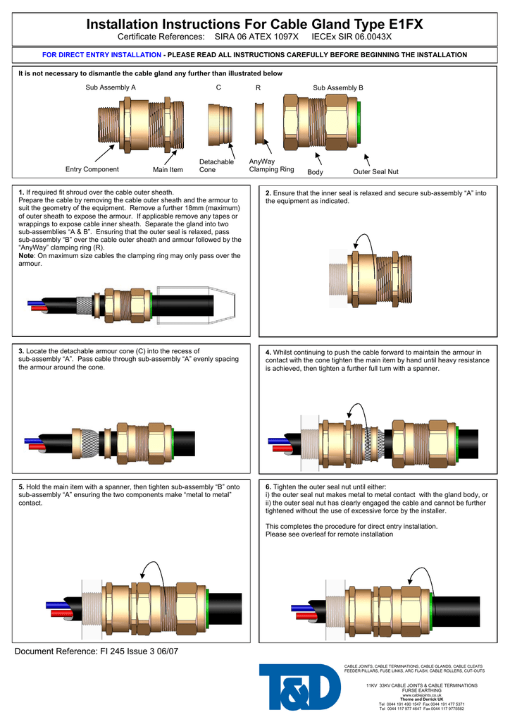
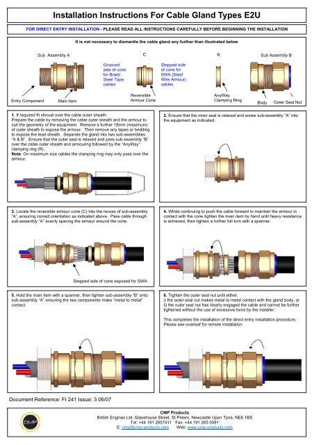
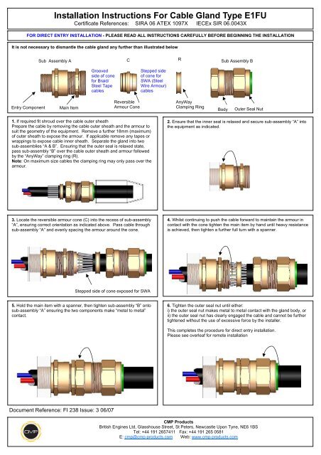
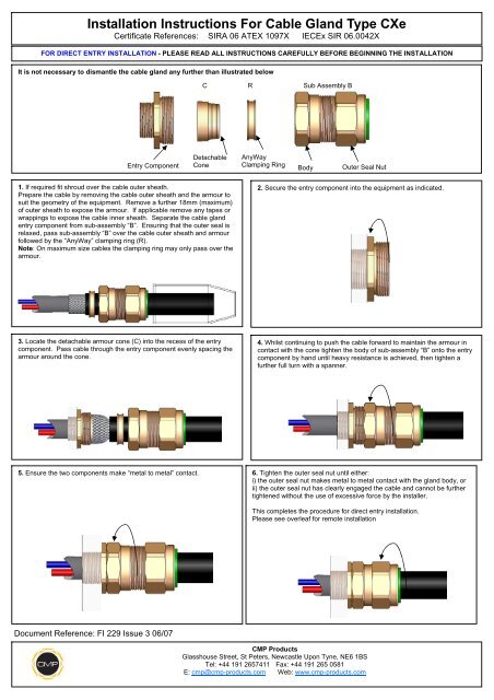
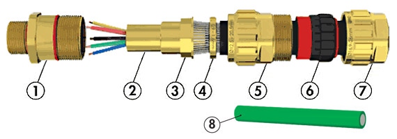
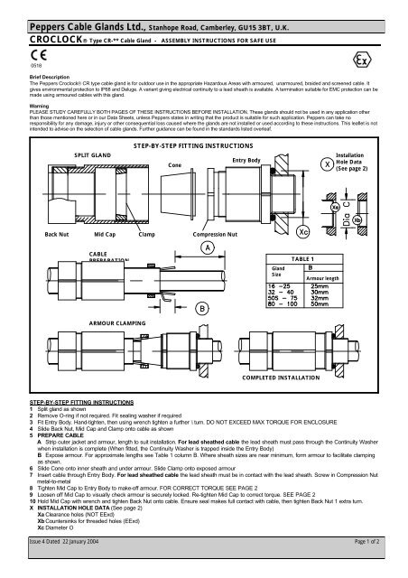
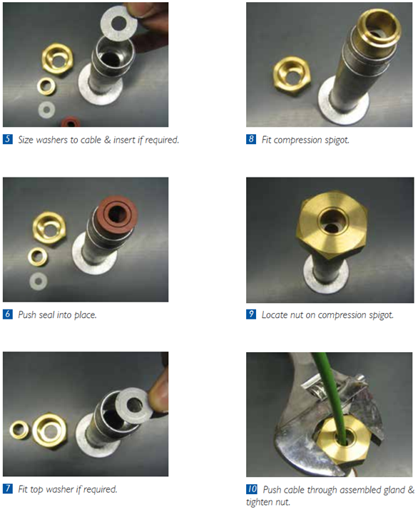
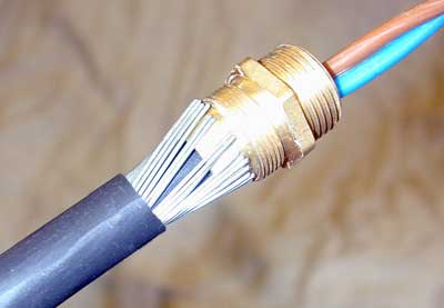
If required fit shroud over the cable outer sheath prepare the cable by removing the cable outer sheath and the armour to suit the geometry of the equipment.
Cable gland installation instructions.
The arrowhead indicating the correct armour thickness or type should point towards the equipment i note.
Installation of cable glands must be carried whilst following the appropriate codes of practice local regulations and in accordance with manufacturer guidelines.
The cable glands when used with braided cable types are only suitable for use with fixed apparatus the cable for which must be effectively clamped and cleated elsewhere.
Assembly fitting instructions for installation of cable gland type t3cds installation instructions 1 select the correct cable gland size using physical dimensions of the cable cross referenced against the selection table opposite.
M20 x 1 5 and m25 x 1 5.
Tape armour must be re trimmed at 90 to the vertical axis of.
For remote installation please read all instructions carefully before beginning the installation installation instructions for cable gland type cx 1.
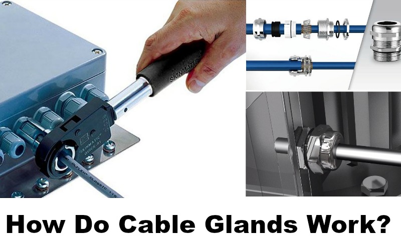
Our installation instructions provide a step by step guide to ensure an easy and efficient installation of our cable glands.
Failure to comply with the instructions below will render the atex iecex certifications invalid.
Installation should only be carried out by a competent person with relevant knowledge and skilled in the installation of cable glands.
Remove a further 18mm maximum 3.
Reversible armour clamping ring rac important.
The cable glands may not be modified by the customer.
Cable gland installation guide installation installation of the cable glands must be completed by a skilled technician or engineer.
Hawke universal cable glands installation instruction 1.
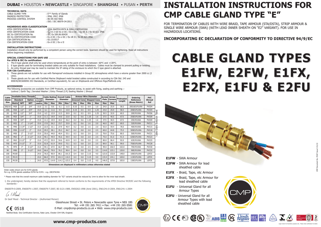
Braid x flat steel wire y steel tape z ring position swa position general identification ring orientation for.
Cable gland installation instructions free download as pdf file pdf text file txt or view presentation slides online.

